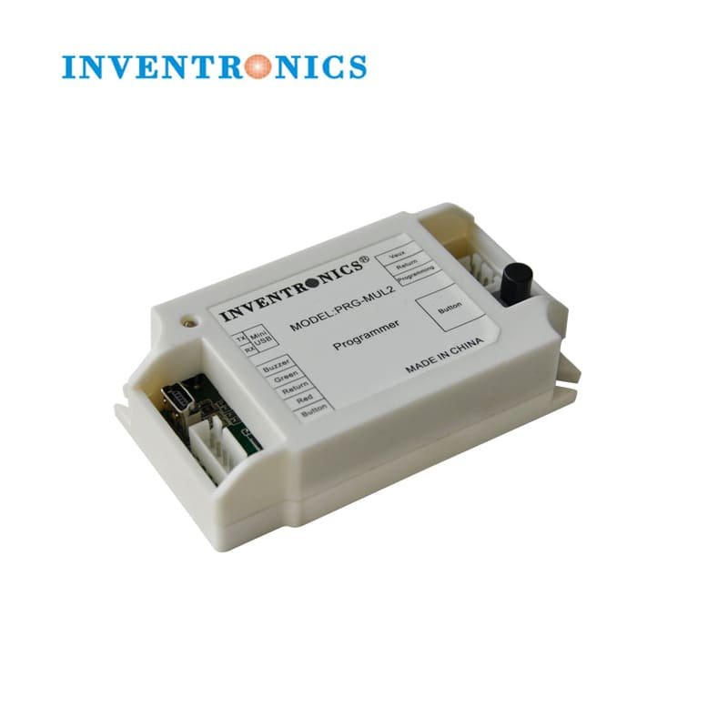
Off-line Programming
At PC end, the upper software can download the configuration to the programmer, then only 5V power supply is needed to program the drivers or controllers.
Automatic Programming
When this function is enabled, after connecting the programming leads to the programmer, it will download the configuration to the controller or driver.
Long Push Button(5s<T<10s), the Automatic function will be disabled or enabled.
When the function has been turned on, the Red LED will flicker 2 times, each time lasts 0.5 second.
When the function has been turned off, the Green LED will flicker 2 times, each
Buzzer
The programmer provides a port for connecting to an external Buzzer if needed.
When programming has finished successfully, the buzzer will beep for 0.5 seconds.
Long Push Button(T>10s), it will enable or disable the buzzer function.
When the buzzer function is enabled by above action, the buzzer will beep 2 second, or it will beep 0.5s that means the function is disabled.
Before starting the programming, the programmer will read the driver model information. If the
configuration model does not match the driver model, the upper software will show fail message, and
the red LED will turn on.
The matching function is selectable at PC end. The default setting is “on”.